Welcome, Guest
Username: Password: Remember me
  • Page:
  • 1

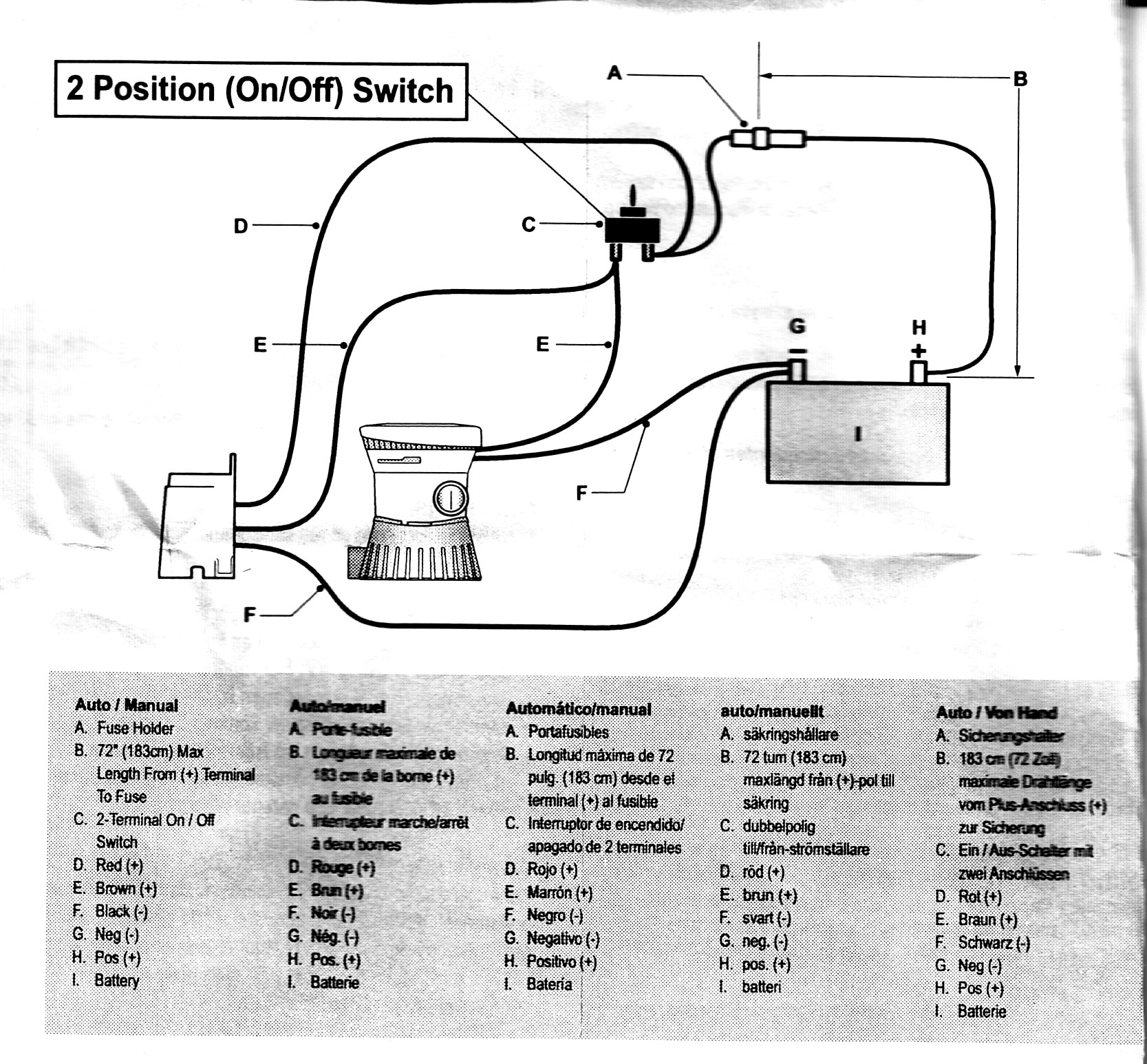
TOPIC: Help with a bilge switch please

Help with a bilge switch please 13 years 9 months ago #21644

  • zonaman
  • zonaman's Avatar Topic Author
  • Offline
  • Junior Boarder
  • Junior Boarder
  • Posts: 75
  • Karma: 3
  • Thank you received: 0
Need some advice wiring an auto bilge switch (refer to attached diagram). The Attwood folks have the brown wire (E) going to the on/off switch (C) on the bilge pump side and the red wire (D) going to the on/off switch on the fuse/power side. That's about 13 feet for each color wire to connect just as the diagram shows. What I would like to know is if I can splice the auto bilge switch into 1. the brown wire any where between the pump and the bilge side of the on/off switch and 2. connect the red wire anywhere between the on/off switch and the fuse?. It would save me several feet of wire if I can.

One more thing, my fuse is longer than the 72" recommended from the battery, it's more like 120" though I'm using 14 awg wire.

Thanks.
Attachments:

Please Log in or Create an account to join the conversation.

Re:Help with a bilge switch please 13 years 9 months ago #21656

I'm having a hard time understanding the questions, but that's just me, I'm sure. I love 12V wiring, but without it right in front of me, it's hard to comment. For the most part, I follow instructions and use the correct gauge of wire.

When you say your fuse is 120" long, do you mean it's a 120" wire with a fuse holder in the middle? Make sure you get the fuse holder someplace handy when you get her all wired up.

Frank

Please Log in or Create an account to join the conversation.

Re:Help with a bilge switch please 13 years 9 months ago #21661

  • Oceans2
  • Oceans2's Avatar
  • Offline
  • Contributing Member
  • Contributing Member
  • Posts: 247
  • Karma: 26
  • Thank you received: 0
If I am understanding yor question correctly you would like to splice wire "E" from the auto switch with wire "E" from the bilge pump and my thought is yes you can.The same can be done with the 2(-) ground wires "F" Although, I would use a junction blocks rather than splice. Using a junction block makes replacing a failed unit much simpler.

Please Log in or Create an account to join the conversation.

Re:Help with a bilge switch please 13 years 9 months ago #21680

  • DelRay
  • DelRay's Avatar
  • Offline
  • Expert Boarder
  • Expert Boarder
  • Posts: 272
  • Karma: 10
  • Thank you received: 0
I would have the fuse as close to the battery as possible!

Please Log in or Create an account to join the conversation.

Re:Help with a bilge switch please 13 years 9 months ago #21685

  • MarkS
  • MarkS's Avatar
  • Offline
  • Moderator
  • Moderator
  • Posts: 5348
  • Karma: 118
  • Thank you received: 5
All good advise given, IMO. The "bottom line" is where the switch is wired into the lines isn't that critical, as long as the basic current paths are as indicated in the directions. I do agree with Pete (DelRay) that the fuse should be as close to the main power source as possible. Should there be a short (or unintended ground-out) anywhere prior to the fuse, disaster is probable.

Please Log in or Create an account to join the conversation.

Mark

Re:Help with a bilge switch please 13 years 9 months ago #21714

  • 63g3
  • Offline
  • Contributing Member
  • Contributing Member
  • Posts: 465
  • Karma: 62
  • Thank you received: 2
I'll assume the Battery/motor Pump and float switch are all in the rear of the boat. If this is the case you will only need one wire running the length of the boat, this will cover the +12 for manual operation of the pump. For auto float function of the pump all the wiring can be in the back. The dash switch will toggle between Run and auto. Because this is for a 2 pole switch there is no way to have everything off. At best it'll be in the auto mode at the ready. I think this arrangement is fine. BUT, it is not uncommon to have a three position switch in the dash where you can choose either Run or auto like the two pole above and the third is everything off.
For the above diagram:

B can be a fused jumper from +12 somewhere on the dash, to one side of the dash switch, so that is a short run.
D is a fused jumper to +12 from the motor or Battery to the float so that is a short run.
E is the long wire from the other pole on the dash switch to the
pump. You can splice in the Float switch wire to this near the
pump, so tha tis another short wire.
F picks up ground from the motor or Battery and both the float and the pump can be spliced together so that whould not be a long run either.

SO one long wire and two fused lines are needed. One in the dash, one in the rear. The diagram is awkward because they are trying only to use one fuse for both sides, there is a logic to that but requires longer runs of wiring.
Hope this helped.
Randy

Please Log in or Create an account to join the conversation.

  • Page:
  • 1
Time to create page: 0.315 seconds

Donate

Please consider supporting our efforts.

Glassified Ads

Fenders - Tee Nee trailer
( / Parts / Miscellaneous)

noimage
09-30-2024

1958 Skagit Sportster
( / Boats)

1958 Skagit Sportster
09-25-2024

Winner Marauder - the classic 1970 runabout!
( / Boats)

Winner Marauder - the classic 1970 runabout!
09-16-2024

FG Login

FiberGoogle

Who's Online

We have 6348 guests and no members online