Welcome, Guest
Username: Password: Remember me
  • Page:
  • 1

TOPIC: Alternator Wiring?

Alternator Wiring? 11 years 1 month ago #85834

  • WizardIII
  • WizardIII's Avatar Topic Author
  • Offline
  • Fresh Boarder
  • Fresh Boarder
  • Posts: 46
  • Karma: 4
  • Thank you received: 0
Just need to be clear on this. I have copies of the owners manual and service manual. Each has a different diagram of the two position switch from the alternator. The OM shows it switching 'between' the yellow and gray wires (with a warning that 'hi' should only be used when current demand is heavy) and the SM shows the switch 'adding' the yellow wire 'to' the gray wire.
I don't have the switch and have connected the y & g wires together at the rectifier.
Yes/No?
Thanks,
WizardIII

Please Log in or Create an account to join the conversation.

Re:Alternator Wiring? 11 years 1 month ago #85935

  • 4stroke
  • 4stroke's Avatar
  • Offline
  • Expert Boarder
  • Expert Boarder
  • Posts: 291
  • Karma: 16
  • Thank you received: 1
Black and gray hooked up to the rectifier gives you about 7 amps for low charging, adding the yellow to the the gray ups the amperage to 15 to 20 for Hi charging. A switch between the yellow and gray gives you the choice of Hi or Low.

Please Log in or Create an account to join the conversation.

Dick Johnson

1989 16ft Sylvan

'57 Evinrude 18 (finally found a decent one)
'58 Johnson 5.5
'72 Johnson 6.0
'61 Homelite
'64 Johnson 18
'65 Homelite 55
'66 Homelite 55
'68 Bearcat 55 (3)
'70 Bearcat 55 (2)
'71 Bearcat 85 (Sold)

Re:Alternator Wiring? 11 years 1 month ago #85985

  • WizardIII
  • WizardIII's Avatar Topic Author
  • Offline
  • Fresh Boarder
  • Fresh Boarder
  • Posts: 46
  • Karma: 4
  • Thank you received: 0
Yes, that's how the service manual shows the schematic. I'm just curious why the owners manual has the switch choosing the gray 'or' black wire, not tying them together. I've been concerned about a possible over-charging problem and don't want to fry anything. I'm going to put an amp gauge in the 20 amp fuse line to monitor the circuit and maybe go back to the hi-low switch since I have very little drain on the system most of the time.
Thanks

Please Log in or Create an account to join the conversation.

Re:Alternator Wiring? 11 years 1 month ago #85992

  • 4stroke
  • 4stroke's Avatar
  • Offline
  • Expert Boarder
  • Expert Boarder
  • Posts: 291
  • Karma: 16
  • Thank you received: 1
If you have all three alternator wires hooked up and have very little drain chances are it will overcharge. The hi/low switch was an option, engines that didn't have this option had a loose unconnected yellow wire. The third wire increases the amperage. It doesn't make any difference which other alternator wire the yellow is connected to (black or gray) as it is now using all of the alternator coils for full output.

Please Log in or Create an account to join the conversation.

Dick Johnson

1989 16ft Sylvan

'57 Evinrude 18 (finally found a decent one)
'58 Johnson 5.5
'72 Johnson 6.0
'61 Homelite
'64 Johnson 18
'65 Homelite 55
'66 Homelite 55
'68 Bearcat 55 (3)
'70 Bearcat 55 (2)
'71 Bearcat 85 (Sold)

Re:Alternator Wiring? 11 years 1 month ago #86215

  • WizardIII
  • WizardIII's Avatar Topic Author
  • Offline
  • Fresh Boarder
  • Fresh Boarder
  • Posts: 46
  • Karma: 4
  • Thank you received: 0
I appreciate the info Dick and have decided to add the hi/lo switch to help keep my amps 'regulated'. I'm not a restorer per se but I do like to keep things original if I can.
I have been trolling the usual channels for the hi/lo switch and bracket with no luck so far. Would you have a spare to sell?
Thanks, Steve
Talent, OR.

Please Log in or Create an account to join the conversation.

Re:Alternator Wiring? 11 years 1 month ago #86556

  • WizardIII
  • WizardIII's Avatar Topic Author
  • Offline
  • Fresh Boarder
  • Fresh Boarder
  • Posts: 46
  • Karma: 4
  • Thank you received: 0
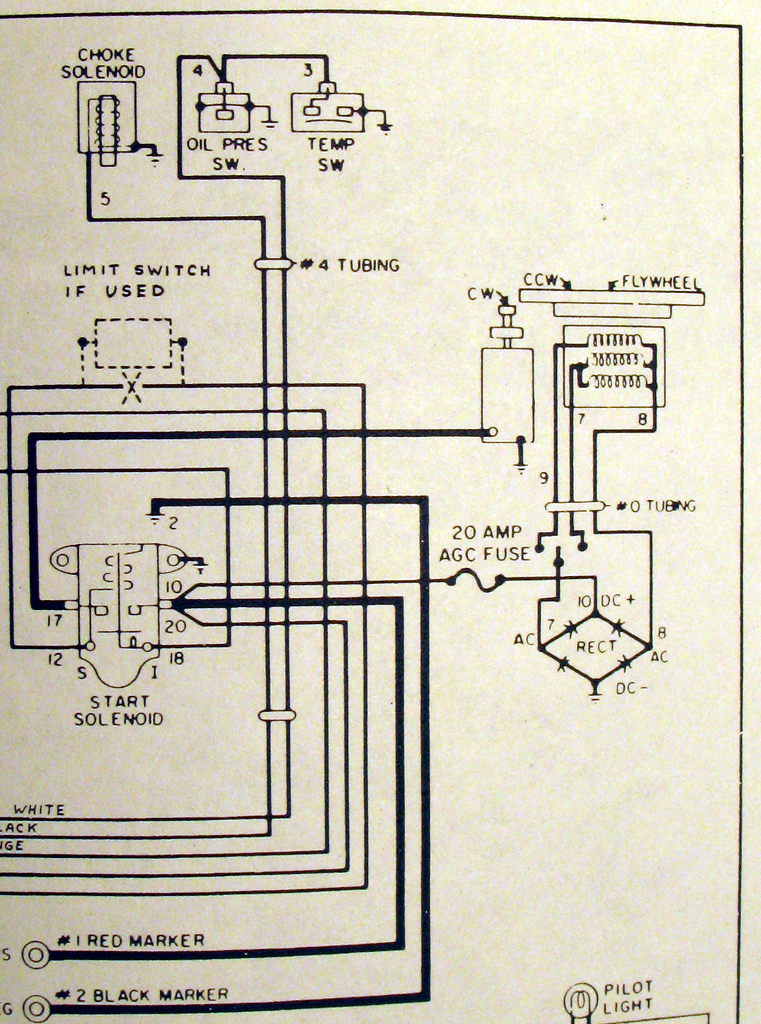
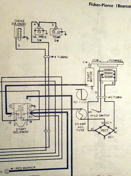
Going to take another stab at clearing this up in my mind. I'm, hopefully, adding two photo's of the wiring for the two position regulator switch from the OM & SM.
As you can see one has the switch 'adding' the black to the gray and the other chooses 'between' the two.
Any thoughts on this?
I'm still going to add the switch and now see where it was originally mounted on the starter bracket.
Thanks for any info,
Steve - WizardIII
Attachments:

Please Log in or Create an account to join the conversation.

Re:Alternator Wiring? 11 years 1 month ago #86558

  • WizardIII
  • WizardIII's Avatar Topic Author
  • Offline
  • Fresh Boarder
  • Fresh Boarder
  • Posts: 46
  • Karma: 4
  • Thank you received: 0
Well, one came through. Hopefully here is the other.

Please Log in or Create an account to join the conversation.

Re:Alternator Wiring? 11 years 1 month ago #86559

  • WizardIII
  • WizardIII's Avatar Topic Author
  • Offline
  • Fresh Boarder
  • Fresh Boarder
  • Posts: 46
  • Karma: 4
  • Thank you received: 0
OK, that didn't work. I'll try smaller images.
Attachments:

Please Log in or Create an account to join the conversation.

Re:Alternator Wiring? 11 years 4 weeks ago #86755

  • 4stroke
  • 4stroke's Avatar
  • Offline
  • Expert Boarder
  • Expert Boarder
  • Posts: 291
  • Karma: 16
  • Thank you received: 1
Steve,
I don't have a bracket, I've made mine. As far as your first diagram, I've never seen that one, all of the diagrams I have show either the voltage regulator or the hi/lo option connecting the black to the gray. Your second diagram is the one shown in the several different diagrams I have. This system is very similar to Honda motorcycles of the early '60's, both systems do not use all the charging coils for lower amperage. On the Honda, where the lights are turned on the unused coils are now in use to help increase amperage when the draw is greater. The Homelite does the same with a manual switch. I'm thinking the first diagram is a misprint and I can see where this is confusing.

Please Log in or Create an account to join the conversation.

Dick Johnson

1989 16ft Sylvan

'57 Evinrude 18 (finally found a decent one)
'58 Johnson 5.5
'72 Johnson 6.0
'61 Homelite
'64 Johnson 18
'65 Homelite 55
'66 Homelite 55
'68 Bearcat 55 (3)
'70 Bearcat 55 (2)
'71 Bearcat 85 (Sold)

Re:Alternator Wiring? 11 years 4 weeks ago #86776

  • billr
  • billr's Avatar
  • Offline
  • Moderator
  • Moderator
  • Posts: 621
  • Karma: 51
  • Thank you received: 0
There are a few different versions of that drawing.
Some are just plain electrically incorrect.

The bottom line is, there is no OEM regulator except for the first series of motors in 61/62. I think I still have a new in the box regulator etc for one of those.
The hi/lo switch is not necessary.
The late F model, usually the blue blocks, did away with the switch and you just either connected the gray or the black wire to one AC connection on the rectifier, yellow on the other AC connection of course.

Each of those alternator windings is nominal 5-7amps of charge capacity. So with one winding connected to the rectifier, 5-7amp charge rate max.
With the other leg comprised of two windings connected, you have a 10-14amp max charge rate.
If you connect all three windings to the rectifier, then you have nominal 15-21amp charge rate.
The charge rate varies with speed of rotation, strength of magnets in the flywheel if in original configuration with only a rectifier.

Some of the guys on the big houseboats on Lake Shasta use all three windings as they have lots of lights, fans, heaters etc.
However, without a regulator running all three or sometimes even two windings connected it is common to see batteries overcharged and loss of water etc. I've sold a bunch of new alternators to those guys down there.
(crazy stuff happens on that lake, I've had two boats that had the water intake tube corrode through, in freshwater of all places, and all manner of other crazy failures)
So, if you want to install a switch you can but it is not necessary at all and in fact the blue F blocks did without it and you manually just connected either one or two windings direct to the rectifier terminal via a spade connection.
For most boats, you only need one winding connected to maintain your battery in a ready to start the motor condition.
That's what I run on my Bearcat, one winding connected one just wire tied and taped so it cannot short to the block.
No switch to f with, or forget, etc.

Please Log in or Create an account to join the conversation.

Re:Alternator Wiring? 11 years 3 weeks ago #86875

  • 4stroke
  • 4stroke's Avatar
  • Offline
  • Expert Boarder
  • Expert Boarder
  • Posts: 291
  • Karma: 16
  • Thank you received: 1
I run mine with all three connected via Hi/Lo switch. Having had a my battery drained a couple times the first year I ran the engine it's a must for me. The live well pump I'm sure uses the most power of everything I have turned on, then the radios, depth sounder, etc. I am also the majority of the time only turning 500-600 rpm. With the switch I have the option to drop the amperage down when I decide to go cruising. These engines rope start very easy (CCW), don't ask how I know!

Please Log in or Create an account to join the conversation.

Dick Johnson

1989 16ft Sylvan

'57 Evinrude 18 (finally found a decent one)
'58 Johnson 5.5
'72 Johnson 6.0
'61 Homelite
'64 Johnson 18
'65 Homelite 55
'66 Homelite 55
'68 Bearcat 55 (3)
'70 Bearcat 55 (2)
'71 Bearcat 85 (Sold)

Re:Alternator Wiring? 11 years 3 weeks ago #86899

  • billr
  • billr's Avatar
  • Offline
  • Moderator
  • Moderator
  • Posts: 621
  • Karma: 51
  • Thank you received: 0
I had the opportunity to rope start mine today, but declined haha.
I ran mine in the evil saltwater again today, where she's been sitting since July.
Darned thing fires right up, idles nice, runs fine. No smoke, no smell. Was a nice run today.

Please Log in or Create an account to join the conversation.

Re:Alternator Wiring? 11 years 3 weeks ago #86907

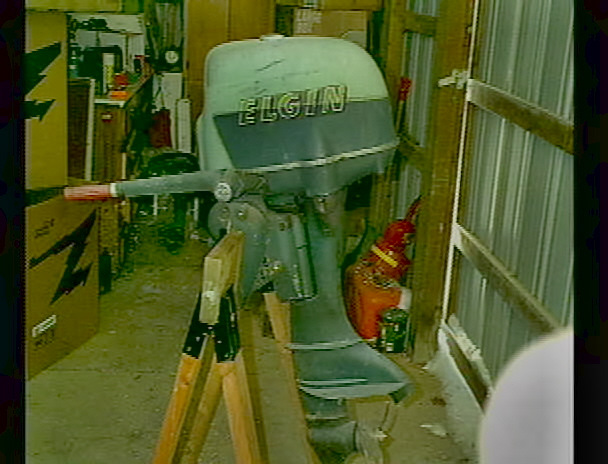
Didn't use mine last season. Hope to next season. Used daughters pontoon. Powered by a 89 Mariner Classic 45 w/trim and tilt.
Happy Holidays Bill, and thanks for all of your help. PS: Our lake is froze over already.
Elgindave
Attachments:

Please Log in or Create an account to join the conversation.

Re:Alternator Wiring? 11 years 3 weeks ago #86915

  • billr
  • billr's Avatar
  • Offline
  • Moderator
  • Moderator
  • Posts: 621
  • Karma: 51
  • Thank you received: 0
No kidding Dave, already for some ice fishing in January or so?
You should post a pic of summer boating and winter with the trucks out on the lake so everyone can see the crazy difference in the seasons. I still remember when you first sent me those pics, haha.

Please Log in or Create an account to join the conversation.

Re:Alternator Wiring? 11 years 3 weeks ago #86934

Will do Bill
Attachments:

Please Log in or Create an account to join the conversation.

Re:Alternator Wiring? 11 years 3 weeks ago #86935

  • billr
  • billr's Avatar
  • Offline
  • Moderator
  • Moderator
  • Posts: 621
  • Karma: 51
  • Thank you received: 0
Sorry to hijack the alternator thread :(

Dave, is that the lake behind you? Pic from last year or right now?
Is that a beer on the seat?

Please Log in or Create an account to join the conversation.

Re:Alternator Wiring? 11 years 3 weeks ago #86958

  • WizardIII
  • WizardIII's Avatar Topic Author
  • Offline
  • Fresh Boarder
  • Fresh Boarder
  • Posts: 46
  • Karma: 4
  • Thank you received: 0
I think you are correct. The first image must be a misprint. I have seen that many times with my radio manuals. Although it made more sense to me at first (choosing 1 or 2 coils) I see now that with each coil pumping about 5 amps tying them together gets the max 15 or so amps out.
I'm going install the switch anyway because, well, I just like switches.
Thanks for the input.
Steve

Please Log in or Create an account to join the conversation.

Re:Alternator Wiring? 11 years 3 weeks ago #86959

  • WizardIII
  • WizardIII's Avatar Topic Author
  • Offline
  • Fresh Boarder
  • Fresh Boarder
  • Posts: 46
  • Karma: 4
  • Thank you received: 0
BTW, that post was a reply to Dick Johnson.
WizardIII

Please Log in or Create an account to join the conversation.

Re:Alternator Wiring? 11 years 3 weeks ago #86961

  • WizardIII
  • WizardIII's Avatar Topic Author
  • Offline
  • Fresh Boarder
  • Fresh Boarder
  • Posts: 46
  • Karma: 4
  • Thank you received: 0
billr wrote:

There are a few different versions of that drawing.
Some are just plain electrically incorrect.

The bottom line is, there is no OEM regulator except for the first series of motors in 61/62. I think I still have a new in the box regulator etc for one of those.
The hi/lo switch is not necessary.
The late F model, usually the blue blocks, did away with the switch and you just either connected the gray or the black wire to one AC connection on the rectifier, yellow on the other AC connection of course.

Each of those alternator windings is nominal 5-7amps of charge capacity. So with one winding connected to the rectifier, 5-7amp charge rate max.
With the other leg comprised of two windings connected, you have a 10-14amp max charge rate.
If you connect all three windings to the rectifier, then you have nominal 15-21amp charge rate.
The charge rate varies with speed of rotation, strength of magnets in the flywheel if in original configuration with only a rectifier.

Some of the guys on the big houseboats on Lake Shasta use all three windings as they have lots of lights, fans, heaters etc.
However, without a regulator running all three or sometimes even two windings connected it is common to see batteries overcharged and loss of water etc. I've sold a bunch of new alternators to those guys down there.
(crazy stuff happens on that lake, I've had two boats that had the water intake tube corrode through, in freshwater of all places, and all manner of other crazy failures)
So, if you want to install a switch you can but it is not necessary at all and in fact the blue F blocks did without it and you manually just connected either one or two windings direct to the rectifier terminal via a spade connection.
For most boats, you only need one winding connected to maintain your battery in a ready to start the motor condition.
That's what I run on my Bearcat, one winding connected one just wire tied and taped so it cannot short to the block.
No switch to f with, or forget, etc.

_________________________________________________________________________________________________

Thanks Bill, I think I've got it. Between you and 4stroke I agree with the misprint and understand that tying all three coils together gets the max amp output. I know I don't need the hi/lo switch but I'm a radio guy and like knobs and switches. Besides, although I'm sure I will always run on low I might want to install that 150 watt stereo to just to add to everyone's enjoyment at the lake.
Interesting trivia about Lake Shasta. Some in Redding refer to it as a cess-pool which may be worse than salt water.

Please Log in or Create an account to join the conversation.

Re:Alternator Wiring? 11 years 3 weeks ago #86962

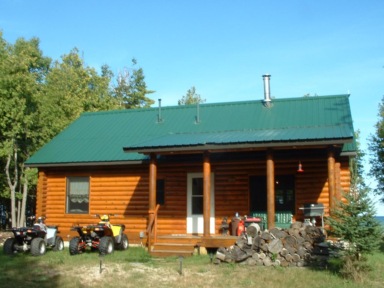
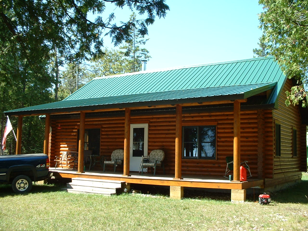
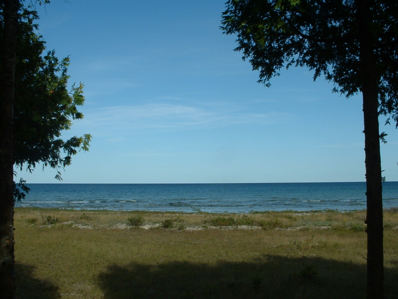
Hi Bill, Yes it is empty. Lake Michigan in the back round. Taken about 8 years ago. It is Lake Michigan in the backround
In the U.P. near my cabin.


I only use two wires from the alternator and it keeps things charged up ok for me. I don't run too many things on the pontoon.

Last photo. view from front porch.
Attachments:

Please Log in or Create an account to join the conversation.

  • Page:
  • 1
Time to create page: 0.222 seconds

Donate

Please consider supporting our efforts.

Glassified Ads

1956 Lonestar Meteor
( / Boats)

1956 Lonestar Meteor
12-24-2024

Mercury outboard
( / Engines)

noimage
11-03-2024

Classic Mercury Outboard Motors
( / Engines)

Classic Mercury Outboard Motors
10-18-2024

FG Login

FiberGoogle

Who's Online

We have 10992 guests and no members online